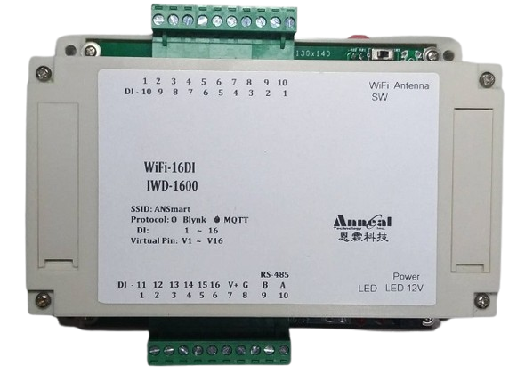
DIO-1600 (16 Port Digital Input Device) provides 16 digital input ports.
DIO-1600 device can transmit the digital values (Binary 0 or 1) using (1) MQTT/WiFi and (2) WiFi techniques. Method (1) sends MQTT messages to the remote MQTT broker directly. Methods (2) requires to work with the MQTT server. Messages processed in the MQTT Server can be displayed in the remote PC monitor via a private VPN link.
LoRa technique is not designed in this device.
Hardware Features
DIO-1600 device
WiFi Specification
Power Supply
16 Port Digital Inputs
IEEE 802.11b/g/n, 2.4 GHz, transmit power 18 dBm
DC 12V
Software Features
Message Protocol
Push Notification
MQTT, JSON
LINE Notify
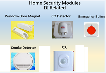
Digital Input Modules
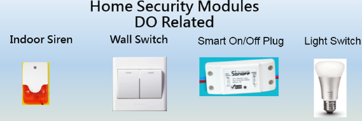
Digital Output Modules
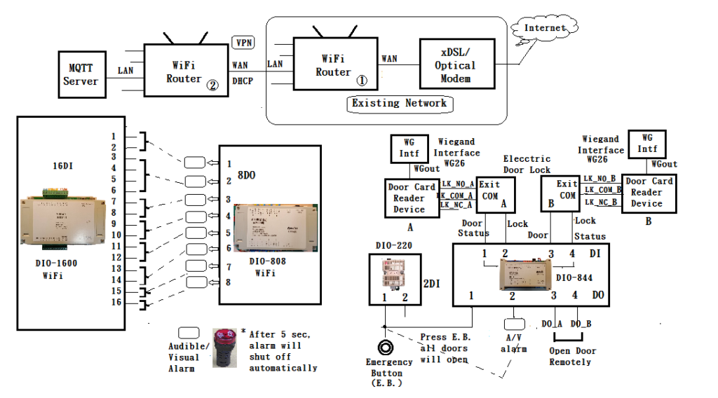
DIO Devices with WiFi
DIO devices can receive/transmit the digital values (Binary 0 or 1) using JSON format encapsulated in WiFi packets. Each DIO signal consists of sensor device name (D22, D44, D08, D16), ID number (D1 ~ Di), Sequence number, each DI or DO name and the associated binary data consecutively in JSON format. In this examle, DIO-1600, DIO-808, DIO-844 and DIO-220 are used.
DIO-1600 provides 16 digital input ports to monitor the 16 door status (door open or close).
DIO-808 provides 8 digital output ports to trigger alarms when the door is open. Doors 1 and 2 share the alarm provided by DO1. Doors 3 ~ 6 share the alarm provided by DO2, and so on as shown in the figure. All 16 doors trigger the associated alarms by the 8 DO outputs. Alarm can shut off by itself automatically after 5 seconds (configurable). DO port can be turned on/off in the Graphic Interface.
The 4 digital inputs in DIO-844 monitor the door and lock status from the two electric door locks. DO1 is connected to the Emergency Button (E.B.), DO2 is used to trigger alarms for the two door status. DO3 and DO4 are used to open/close doors remotely in the Graphic interface.
Two Door Card Reader Devices (A and B) are connected to the two Electric Door Locks respectively. Two Wiegand Interfaces (A and B) receives Wiegand output (26bit) from the Door Card Reader Device and send the ID number to the MQTT Server (MQSVR) for processing.
DIO-220 uses DI1 to connect in parallel with DO1 in DIO-844 to sense the digital output message sent from the Graphic interface and also from manual press of the Emergency Button.
MQTT server receives status (DI port) and Wiegand ID number from Wiegand Interface. MQTT server also transmits command to trigger alarms in the DIO-808 and open/close doors in the DIO-844.
Messages processed in the MQTT Server can be displayed locally or in the remote PC monitor via a private VPN link. The Graphic Interface is a two dimension floor plan with icons to show the status of each DI or DO ports as shown in the figure.